What Parameters Are Important When Diagnosing The Body Electronics System?
Diagnosing the body electronics system is crucial for maintaining a vehicle’s safety, comfort, and overall performance, and CARDIAGTECH.NET provides the tools and expertise needed to master this essential aspect of automotive repair. By focusing on key parameters such as voltage, current, resistance, and communication protocols, technicians can accurately pinpoint issues and ensure optimal vehicle operation. Let’s explore the essential parameters for effectively diagnosing body electronics systems, enhancing your diagnostic skills, and ensuring customer satisfaction.
1. Understanding the Body Electronics System
1.1 What is the Body Electronics System?
The body electronics system in a vehicle encompasses all the electronic components that control non- Powertrain functions, enhancing comfort, convenience, and safety. This system includes a wide array of components such as lighting, door locks, windows, security systems, infotainment, and climate control.
1.2 Why is Diagnosing Body Electronics Important?
Diagnosing body electronics is vital because these systems directly impact the driving experience and safety. According to a study by the National Highway Traffic Safety Administration (NHTSA) in 2023, malfunctions in body electronics can lead to safety hazards. Accurate diagnostics ensure these systems function correctly, preventing potential risks and enhancing vehicle reliability.
1.3 Common Issues in Body Electronics Systems
Common problems include faulty sensors, wiring issues, module failures, and software glitches. These can manifest as malfunctioning lights, inoperative power windows, unresponsive door locks, or issues with the infotainment system. Addressing these issues promptly ensures vehicle safety and comfort. At CARDIAGTECH.NET, we understand these challenges and provide the tools necessary to diagnose and repair them efficiently.
2. Essential Parameters for Diagnosing Body Electronics
2.1 Voltage
2.1.1 What is Voltage and Why is it Important?
Voltage is the electrical potential difference that drives current through a circuit. Proper voltage levels are essential for the correct operation of electronic components. According to the Electrical Engineering Handbook, maintaining correct voltage is crucial for the stability and reliability of electronic systems.
2.1.2 How to Measure Voltage
Use a multimeter to measure voltage at various points in the circuit. Compare the readings to the specified values in the vehicle’s service manual. A significant deviation indicates a potential issue, such as a short circuit or open circuit. CARDIAGTECH.NET offers high-quality multimeters for accurate voltage measurements.
2.1.3 Common Voltage Issues
Voltage drops can occur due to corroded connectors, damaged wiring, or faulty grounds. Overvoltage can damage sensitive electronic components. Identifying and resolving these issues is crucial for maintaining the system’s integrity.
2.2 Current
2.2.1 What is Current and Why is it Important?
Current is the flow of electrical charge through a circuit. Monitoring current helps identify excessive draw or unexpected drops, indicating potential problems within the system. “Understanding current flow is fundamental to diagnosing electrical issues,” notes the Automotive Electronics Council in their 2022 guidelines.
2.2.2 How to Measure Current
Use an ammeter to measure current in series with the circuit. Clamp meters can also be used to measure current without breaking the circuit. Compare the measured current to the specified values. CARDIAGTECH.NET provides a range of ammeters and clamp meters for precise current measurements.
2.2.3 Common Current Issues
Excessive current draw can indicate a short circuit or a component drawing too much power. Low current can indicate a high-resistance connection or a faulty component. Diagnosing these issues ensures the system operates efficiently and safely.
2.3 Resistance
2.3.1 What is Resistance and Why is it Important?
Resistance is the opposition to the flow of current in a circuit. Measuring resistance helps identify faulty components, damaged wiring, or poor connections. “Accurate resistance measurements are key to pinpointing electrical faults,” according to a 2021 report by the Institute of Electrical and Electronics Engineers (IEEE).
2.3.2 How to Measure Resistance
Use a multimeter to measure resistance with the circuit de-energized. Check the resistance of wiring, connectors, and components. Compare the readings to the specified values. CARDIAGTECH.NET offers precision multimeters for accurate resistance testing.
2.3.3 Common Resistance Issues
High resistance can result from corrosion, loose connections, or damaged wiring, leading to voltage drops and component malfunction. Low resistance can indicate a short circuit. Proper resistance testing is essential for diagnosing these issues accurately.
2.4 Communication Protocols
2.4.1 What are Communication Protocols and Why are They Important?
Communication protocols, such as CAN (Controller Area Network), LIN (Local Interconnect Network), and Ethernet, enable different electronic control units (ECUs) to communicate with each other. These protocols ensure seamless data exchange between modules, facilitating coordinated system operation.
2.4.2 Common Communication Protocols in Automotive Systems
- CAN (Controller Area Network): Used for critical systems like engine management, ABS, and transmission control.
- LIN (Local Interconnect Network): Used for less critical systems like door locks, windows, and lighting.
- Ethernet: Increasingly used for high-bandwidth applications such as infotainment and advanced driver-assistance systems (ADAS).
2.4.3 How to Diagnose Communication Issues
Use a diagnostic scan tool to check for communication errors and diagnostic trouble codes (DTCs). Analyze the data stream to identify modules that are not communicating correctly. CARDIAGTECH.NET provides advanced diagnostic tools to effectively diagnose communication issues.
2.4.4 Common Communication Issues
Communication problems can arise from wiring faults, module failures, or software glitches. These issues can disrupt the entire system, leading to multiple malfunctions. Accurate diagnosis and repair of communication issues are crucial for restoring proper system function.
2.5 Signal Integrity
2.5.1 What is Signal Integrity and Why is it Important?
Signal integrity refers to the quality of the electrical signal as it travels through a circuit. Maintaining good signal integrity ensures accurate data transmission between electronic components, which is essential for reliable system operation. According to a study by Clemson University’s Department of Automotive Engineering in 2022, poor signal integrity can lead to intermittent faults and system instability.
2.5.2 Factors Affecting Signal Integrity
- Noise: Electrical interference that can distort the signal.
- Reflections: Signal reflections caused by impedance mismatches.
- Attenuation: Signal loss over distance.
- Crosstalk: Interference from adjacent signals.
2.5.3 How to Test Signal Integrity
Use an oscilloscope to examine the signal waveform. Look for distortions, noise, or attenuation. Time-domain reflectometry (TDR) can be used to identify impedance mismatches and cable faults. CARDIAGTECH.NET offers advanced oscilloscopes and TDR equipment for thorough signal integrity testing.
2.5.4 Common Signal Integrity Issues
Poor signal integrity can result from damaged wiring, loose connections, or electromagnetic interference (EMI). Addressing these issues ensures reliable communication between electronic modules.
3. Diagnostic Tools and Equipment
3.1 Multimeters
3.1.1 Importance of a Quality Multimeter
A high-quality multimeter is essential for measuring voltage, current, and resistance accurately. Investing in a reliable multimeter ensures precise diagnostics and prevents misdiagnosis.
3.1.2 Features to Look For in a Multimeter
- Auto-ranging: Automatically selects the appropriate measurement range.
- High accuracy: Provides precise readings.
- Continuity testing: Quickly checks for open circuits.
- Diode testing: Tests the functionality of diodes.
- Min/Max recording: Captures the minimum and maximum values of a signal.
CARDIAGTECH.NET offers a range of multimeters with these features to meet your diagnostic needs.
3.2 Scan Tools
3.2.1 What is a Scan Tool and Why is it Important?
A scan tool is a diagnostic device that interfaces with the vehicle’s computer system to read diagnostic trouble codes (DTCs), access live data, and perform system tests. It is an indispensable tool for diagnosing complex electronic issues.
3.2.2 Types of Scan Tools
- Code readers: Basic tools that read and clear DTCs.
- Professional scan tools: Advanced tools that offer bi-directional control, data streaming, and system programming.
- OEM scan tools: Manufacturer-specific tools that provide the most comprehensive diagnostic capabilities.
CARDIAGTECH.NET provides a variety of scan tools to suit different diagnostic requirements.
3.2.3 Key Features of a Scan Tool
- DTC reading and clearing: Retrieves and clears diagnostic trouble codes.
- Live data streaming: Displays real-time data from sensors and modules.
- Bi-directional control: Allows technicians to control and test various components.
- System programming: Enables reprogramming and updating of ECUs.
3.3 Oscilloscopes
3.3.1 What is an Oscilloscope and Why is it Important?
An oscilloscope is a device that displays electrical signals as a waveform, allowing technicians to visualize and analyze signal behavior. It is essential for diagnosing complex electronic circuits and signal integrity issues.
3.3.2 Key Features of an Oscilloscope
- High bandwidth: Captures high-frequency signals accurately.
- Multiple channels: Allows simultaneous monitoring of multiple signals.
- Advanced triggering: Captures specific events for detailed analysis.
- Digital storage: Stores waveforms for later analysis.
CARDIAGTECH.NET offers advanced oscilloscopes with these features for in-depth diagnostics.
3.4 Wiring Diagrams and Service Manuals
3.4.1 Importance of Wiring Diagrams
Wiring diagrams provide detailed information about the vehicle’s electrical circuits, including wire colors, component locations, and circuit layouts. They are essential for tracing circuits and identifying faults.
3.4.2 How to Use Wiring Diagrams Effectively
- Understand the symbols: Familiarize yourself with the symbols used in the diagrams.
- Trace the circuit: Follow the circuit from the power source to the component.
- Identify common fault locations: Look for connectors, splices, and ground points.
3.4.3 Service Manuals
Service manuals provide detailed procedures for diagnosing and repairing specific systems and components. They include specifications, test procedures, and troubleshooting guides.
3.5 CAN Bus Analyzers
3.5.1 What is a CAN Bus Analyzer and Why is it Important?
A CAN bus analyzer is a diagnostic tool used to monitor and analyze the data traffic on a vehicle’s Controller Area Network (CAN) bus. It helps technicians identify communication issues, diagnose network faults, and ensure proper data transmission between electronic control units (ECUs). According to a 2023 report by the Society of Automotive Engineers (SAE), CAN bus analyzers are crucial for diagnosing complex automotive electronic systems.
3.5.2 Key Features of a CAN Bus Analyzer
- Data capture: Records CAN bus traffic for analysis.
- Filtering: Filters specific messages for focused diagnostics.
- Error detection: Identifies communication errors and faults.
- Simulation: Simulates ECU behavior for testing purposes.
3.5.3 How to Use a CAN Bus Analyzer
- Connect the analyzer: Connect the CAN bus analyzer to the vehicle’s diagnostic port.
- Capture data: Record CAN bus traffic while the system is operating.
- Analyze the data: Use the analyzer’s software to identify communication errors, missing messages, or incorrect data.
- Troubleshoot: Based on the analysis, troubleshoot the identified issues by checking wiring, connectors, and ECU functionality.
CARDIAGTECH.NET offers a range of CAN bus analyzers with advanced features to streamline your diagnostic process.
4. Step-by-Step Diagnostic Procedures
4.1 Initial Inspection
4.1.1 Visual Inspection
Begin with a thorough visual inspection of the system. Look for damaged wiring, corroded connectors, and signs of physical damage to components.
4.1.2 Checking Fuses and Relays
Check all relevant fuses and relays. Use a multimeter to verify continuity. Replace any blown fuses or faulty relays.
4.2 Diagnostic Trouble Code (DTC) Retrieval
4.2.1 Connecting the Scan Tool
Connect the scan tool to the vehicle’s diagnostic port (OBD-II port).
4.2.2 Reading DTCs
Retrieve the diagnostic trouble codes (DTCs) from the vehicle’s computer system. Record all DTCs and their descriptions.
4.2.3 Interpreting DTCs
Use the service manual or a reliable online resource to interpret the DTCs. Understand the possible causes and recommended diagnostic procedures.
4.3 Component Testing
4.3.1 Identifying the Component to Test
Based on the DTCs and symptoms, identify the component to test.
4.3.2 Using a Multimeter to Test Components
Use a multimeter to measure voltage, current, and resistance of the component. Compare the readings to the specified values in the service manual.
4.3.3 Using an Oscilloscope to Test Signals
Use an oscilloscope to examine the signal waveform of the component. Look for distortions, noise, or attenuation.
4.4 Circuit Testing
4.4.1 Checking for Open Circuits
Use a multimeter to check for continuity in the circuit. An open circuit indicates a break in the wiring or a faulty connection.
4.4.2 Checking for Short Circuits
Use a multimeter to check for shorts to ground or shorts to voltage. A short circuit indicates a wiring fault or a component failure.
4.4.3 Checking for Voltage Drops
Measure the voltage drop across the circuit. Excessive voltage drop indicates high resistance due to corrosion, loose connections, or damaged wiring.
4.5 Module Testing and Programming
4.5.1 Identifying the Module to Test
Based on the DTCs and symptoms, identify the module to test.
4.5.2 Testing Module Inputs and Outputs
Use a scan tool to monitor the module’s inputs and outputs. Verify that the module is receiving the correct signals and sending the correct commands.
4.5.3 Programming and Configuration
Use a scan tool to program or configure the module if necessary. Follow the manufacturer’s instructions carefully.
5. Advanced Diagnostic Techniques
5.1 Data Logging and Analysis
5.1.1 What is Data Logging?
Data logging involves recording real-time data from the vehicle’s sensors and modules over a period. This data can be analyzed to identify intermittent faults and performance issues.
5.1.2 How to Perform Data Logging
Use a scan tool with data logging capabilities to record the desired parameters. Drive the vehicle under various conditions to capture the data.
5.1.3 Analyzing the Data
Use data analysis software to examine the recorded data. Look for anomalies, patterns, and correlations that can help identify the cause of the problem.
5.2 Network Communication Analysis
5.2.1 Monitoring CAN Bus Traffic
Use a CAN bus analyzer to monitor the data traffic on the vehicle’s CAN bus. Look for communication errors, missing messages, or incorrect data.
5.2.2 Identifying Communication Faults
Analyze the CAN bus data to identify communication faults, such as bus-off errors, arbitration errors, and data errors.
5.2.3 Troubleshooting Network Issues
Troubleshoot network issues by checking wiring, connectors, and module functionality. Use wiring diagrams to trace the CAN bus circuits.
5.3 Using Lab Scopes for Advanced Diagnostics
5.3.1 Setting Up the Lab Scope
Connect the lab scope to the appropriate test points in the vehicle’s electrical system. Ensure proper grounding to avoid noise and interference.
5.3.2 Capturing Waveforms
Capture waveforms of relevant signals, such as sensor outputs, actuator controls, and communication signals. Use the lab scope’s triggering functions to capture intermittent or transient events.
5.3.3 Analyzing Waveforms
Analyze the captured waveforms to identify abnormalities, such as signal distortion, noise, incorrect amplitude, or timing issues. Compare the waveforms to known good signals for reference.
5.3.4 Diagnosing Complex Issues
Use the lab scope to diagnose complex issues, such as intermittent faults, sensor failures, actuator malfunctions, and communication problems. Combine lab scope measurements with other diagnostic techniques, such as scan tool data and visual inspection, to pinpoint the root cause of the problem.
6. Common Mistakes to Avoid
6.1 Not Following Diagnostic Procedures
Always follow the recommended diagnostic procedures in the service manual. Skipping steps or making assumptions can lead to misdiagnosis and wasted time.
6.2 Neglecting Visual Inspection
Don’t underestimate the importance of a thorough visual inspection. Many electrical problems can be identified by simply looking for damaged wiring, corroded connectors, or signs of physical damage.
6.3 Not Verifying Repairs
After making a repair, always verify that the problem has been resolved. Use the scan tool to clear DTCs and perform system tests.
6.4 Ignoring Intermittent Issues
Intermittent issues can be challenging to diagnose, but they should not be ignored. Use data logging and advanced diagnostic techniques to capture and analyze these issues.
7. The Future of Body Electronics Diagnostics
7.1 Advancements in Diagnostic Technology
Diagnostic technology is constantly evolving. New tools and techniques are being developed to diagnose complex electronic systems more efficiently and accurately.
7.2 Remote Diagnostics
Remote diagnostics allows technicians to diagnose vehicles remotely, using telematics data and remote access tools. This can save time and reduce the need for on-site visits.
7.3 Artificial Intelligence (AI) in Diagnostics
AI is being used to analyze diagnostic data and provide technicians with insights and recommendations. AI-powered diagnostic tools can help technicians diagnose complex issues more quickly and accurately.
8. Why Choose CARDIAGTECH.NET for Your Diagnostic Needs?
8.1 High-Quality Diagnostic Tools
CARDIAGTECH.NET offers a wide range of high-quality diagnostic tools, including multimeters, scan tools, oscilloscopes, and CAN bus analyzers. Our tools are designed to meet the needs of professional technicians and ensure accurate diagnostics.
8.2 Expert Support and Training
We provide expert support and training to help you get the most out of our diagnostic tools. Our team of experienced technicians is available to answer your questions and provide guidance.
8.3 Competitive Pricing
We offer competitive pricing on all our diagnostic tools. We believe that everyone should have access to high-quality diagnostic equipment at an affordable price.
8.4 Comprehensive Solutions
From initial diagnosis to final repair, CARDIAGTECH.NET provides comprehensive solutions for all your automotive diagnostic needs. Our tools and support services are designed to help you diagnose and repair vehicles quickly and efficiently.
9. Real-World Case Studies
9.1 Case Study 1: Diagnosing a Faulty Window Regulator
- Problem: A customer reports that the power window in their vehicle is not working.
- Diagnosis: Using a multimeter, the technician verifies that there is no voltage at the window motor. A wiring diagram is used to trace the circuit back to the switch. The switch is tested and found to be faulty.
- Solution: The faulty switch is replaced, and the power window is now functioning correctly.
9.2 Case Study 2: Diagnosing a CAN Bus Communication Issue
- Problem: A vehicle has multiple warning lights illuminated on the dashboard, and the scan tool reports several communication errors.
- Diagnosis: A CAN bus analyzer is used to monitor the CAN bus traffic. The analyzer identifies a faulty ECU that is disrupting the communication network.
- Solution: The faulty ECU is replaced, and the communication errors are resolved. The warning lights are no longer illuminated.
9.3 Case Study 3: Using a Lab Scope to Diagnose a Misfire
- Problem: A vehicle is experiencing a misfire, but the scan tool is not providing clear information about the cause.
- Diagnosis: A lab scope is used to capture the ignition waveforms. The waveforms reveal that the ignition coil is not firing correctly.
- Solution: The faulty ignition coil is replaced, and the misfire is resolved.
10. Frequently Asked Questions (FAQs)
10.1 What is the Most Important Parameter to Check When Diagnosing Body Electronics?
While voltage, current, resistance, and communication protocols are all vital, understanding communication protocols is often the most critical. Modern vehicles rely heavily on networked systems, and communication issues can cause a wide range of symptoms.
10.2 How Often Should I Calibrate My Multimeter?
Multimeters should be calibrated annually to ensure accuracy. Regular calibration prevents measurement errors and ensures reliable diagnostics.
10.3 Can I Use a Basic Code Reader for Advanced Diagnostics?
Basic code readers are useful for reading and clearing DTCs, but they lack the advanced features needed for complex diagnostics. Professional scan tools are required for bi-directional control, data streaming, and system programming.
10.4 What is Bi-Directional Control?
Bi-directional control allows technicians to send commands to the vehicle’s modules and components, enabling them to perform tests and verify functionality.
10.5 How Can I Improve My Diagnostic Skills?
Continuously update your knowledge through training courses, workshops, and online resources. Practice using diagnostic tools and techniques on a variety of vehicles.
10.6 What are the Benefits of Using OEM Scan Tools?
OEM scan tools provide the most comprehensive diagnostic capabilities, including access to manufacturer-specific data, system tests, and programming functions.
10.7 How Do I Diagnose Intermittent Electrical Problems?
Intermittent electrical problems require careful data logging and analysis. Use a scan tool with data logging capabilities to record data while driving the vehicle under various conditions.
10.8 What is the Role of Wiring Diagrams in Diagnostics?
Wiring diagrams provide detailed information about the vehicle’s electrical circuits, including wire colors, component locations, and circuit layouts. They are essential for tracing circuits and identifying faults.
10.9 How Can I Prevent Electrical Problems in My Vehicle?
Regular maintenance, such as checking wiring, connectors, and fuses, can help prevent electrical problems. Address any issues promptly to avoid further damage.
10.10 Where Can I Find Reliable Diagnostic Tools and Equipment?
CARDIAGTECH.NET offers a wide range of high-quality diagnostic tools and equipment. We provide expert support and competitive pricing to meet your diagnostic needs.
Effectively diagnosing the body electronics system requires a comprehensive understanding of key parameters, the right tools, and systematic procedures. By mastering these elements, technicians can accurately identify and resolve issues, ensuring vehicle safety, comfort, and reliability. At CARDIAGTECH.NET, we are committed to providing the tools and expertise you need to excel in automotive diagnostics.
Are you ready to elevate your diagnostic capabilities and ensure customer satisfaction? Contact CARDIAGTECH.NET today at +1 (641) 206-8880 or visit our website at CARDIAGTECH.NET. Our expert team is ready to assist you in selecting the perfect diagnostic tools and providing comprehensive support to meet all your automotive repair needs. Don’t wait—unlock your diagnostic potential with CARDIAGTECH.NET now! Our address is 276 Reock St, City of Orange, NJ 07050, United States.
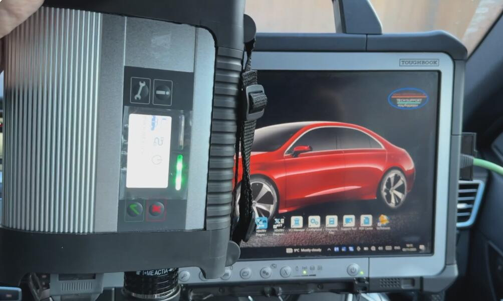
Alt: Modern automotive diagnostic tools, including a scan tool and multimeter, for effective car repair at CARDIAGTECH.NET